

Which Two Dimensional Views Are Standard In An Orthographic Drawing
Fundamentals of Orthographic Views
Figure 4-1 shows an object with its front, top, and right-side orthographic views projected from the object. The views are two-dimensional, so they show no depth. Note that in the projected right plane, there are three rectangles. There is no way to determine which of the three is closest and which is farthest away if only the right-side view is considered. All views must be studied to analyze the shape of the object.
Figure 4-2 shows three orthographic views of a book. After the views are projected they are positioned as shown. The positioning of views relative to one another is critical. The views must be aligned and positioned as shown.
Normal Surfaces
Normal surfaces are surfaces that are at 90° to each other. Figures 4-3, 4-4, and 4-5 show objects that include only normal surfaces and their orthographic views.
-
normal surfaces
-
Surfaces that are 90° to each other.
Hidden Lines
Hidden lines are used to show surfaces that are not directly visible. All surfaces must be shown in all views. If an edge or surface is blocked from view by another feature, it is drawn using a hidden line. Figures 4-6 and 4-7 show objects that require hidden lines in their orthographic views.
Figure 4-8 shows an object that contains an edge line, A-B. In the top view, line A-B is partially hidden and partially visible. The hidden portion of the line is drawn using a hidden-line pattern, and the visible portion of the line is drawn using a solid line.
Figures 4-9 and 4-10 show objects that require hidden lines in their orthographic views.
Precedence of Lines
It is not unusual for one type of line to be drawn over another type of line. Figure 4-11 shows two examples of overlap by different types of lines. Lines are shown on the views in a prescribed order of precedence. A solid line (object or continuous) takes precedence over a hidden line, and a hidden line takes precedence over a centerline.
Slanted Surfaces
Slanted surfaces are surfaces drawn at an angle to each other. Figure 4-12 shows an object that contains two slanted surfaces. Surface ABCD appears as a rectangle in both the top and front views. Neither rectangle represents the true shape of the surface. Each is smaller than the actual surface. Also, none of the views shows enough of the object to enable the viewer to accurately define the shape of the object. The views must be used together for a correct understanding of the object's shape.
-
slanted surfaces
-
Surfaces that are at an angle to each other.
Figures 4-13 and 4-14 show objects that include slanted surfaces. Projection lines have been included to emphasize the importance of correct view location. Information is projected between the front and top views using vertical lines and between the front and side views using horizontal lines.
Compound Lines
A compound line is formed when two slanted surfaces intersect. Figure 4-15 shows an object that includes a compound line.
-
compound line
-
A line that is neither perpendicular nor parallel to the X, Y, or Z axis.
Oblique Surfaces
An oblique surface is a surface that is slanted in two different directions. Figures 4-16 and 4-17 show objects that include oblique surfaces.
-
oblique surface
-
A surface that is slanted in two different directions.
Rounded Surfaces
Figure 4-18 shows an object with two rounded surfaces. Note that as with slanted surfaces, an individual view is insufficient to define the shape of a surface. More than one view is needed to define the surface's shape accurately.
Convention calls for a smooth transition between rounded and flat surfaces; that is, no lines are drawn to indicate the tangency. Inventor includes a line to indicate tangencies between surfaces in the isometric drawings created using the multiview options but does not include them in the orthographic views. Tangency lines are also not included when models are rendered.
Figure 4-19 shows the drawing conventions for including lines for rounded surfaces. If a surface includes no vertical portions or no tangency, no line is included.
Figure 4-20 shows an object that includes two tangencies. Each is represented by a line. Note in Figure 4-20 that Inventor will add tangent lines to the 3D model. These lines will not appear in the orthographic views.
Figure 4-21 shows two objects with similar configurations; however, the boxlike portion of the lower object blends into the rounded portion exactly on its widest point, so no line is required.
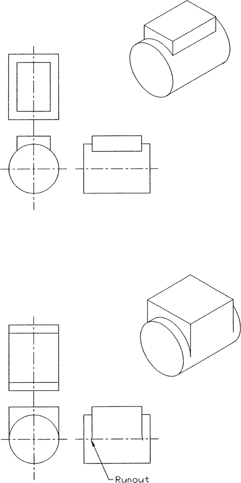
FIGURE 4-21
Which Two Dimensional Views Are Standard In An Orthographic Drawing
Source: https://www.adobepress.com/articles/article.asp?p=2990404&seqNum=2
Posted by: salinasfics1951.blogspot.com
0 Response to "Which Two Dimensional Views Are Standard In An Orthographic Drawing"
Post a Comment